Saike 858D Rework Station - Measurements
The next part in the series about reverse engineering the Saike 858D rework station (Overview) brings a few measurements, I did in my device. It presents me with the problem, that I am not sure anymore if I want to keep the transformer, currently used in the station.
I soldered some wires to the connector of the transformer, allowing me to hook up my Oscilloscope to the transformer output.
10VAC Rail
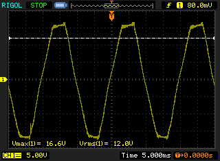
The first measurement is the 10V rail in idle state, without the heater or fan running. The “sine wave” is not really pretty but I don’t really care, given the fact that it will be rectified anyway. The peak output voltage is 16.6 volts, and the RMS output is 12 V instead of 10 V. This means the transformer produces a voltage a bit higher than rated.
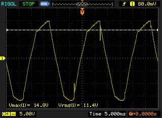
If the fan is running, the 10V rail degrades a bit more and slightly drops in voltage. Again, given the fact that it is fed through a rectifier and then a voltage regulator, that is almost fine.
I don’t really like that we use a voltage of about 12V as the input for the 7805 voltage regulator. We power the microcontroller, the display, the EEPROM and a bit of other stuff from the regulator so I would guess the current is not too high, probably in the few hundreds of mA.
30VAC Rail
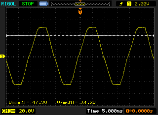
The second rail of the transformer should supply 30VAC. In reality it overshoots quite a bit and delivers 34VAC RMS, peaking at 47 volts. The diodes in the full-bridge rectifier have a 1 volt drop each, so the rectified voltage is probably somewhere close to 45 volts.
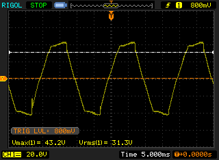
With the fan running, the voltage drops a bit, peaking at 43 volts. This is the voltage, the control circuit for the fan has to regulate to not overload the fan. The fan is labeled with a consumption of 0.35A, which means the transistor has to sink about 4 Watts (11 volts at 0.35A) of heat. As a result, with the fan running, the transistor almost instantly heated up to about 50°C.
Fan output
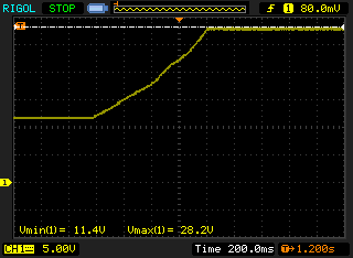
Additionally, I measured the voltage at the output terminal of the fan. At the minimal potentiometer position, the fan has a voltage of 11.4 volts applied to it. At the maximal position, the voltage rises to 28.2 volts, more than 4 volts over the fan specification
Conclusion
I am not really happy with the transformer in the device. The rating is dodgy at best, and lots of energy is wasted in heat in regulation circuits.
At the moment I tend towards replacing the transformer with a 24 volts switching power supply and a small buck converter for the 5 volts logic supply. The fan regulation could then be done through simple PWM.