Measuring Air Quality - Adding a Gas Sensor
At the time, there is quite some discussion regarding air quality and pollution going on in germany. Some cities, like Stuttgart, have to deal with high levels of fine particle emissions. That is why some people came up with a simple solution to build a sensor network for air quality. They provide detailed instruction on how to build your own air quality sensor for about 25 Euros. So, if you want to participate, just head over to luftdaten.info
I have been running my sensor for quite a while now. In addition to fine particles I am also measuring temperature, humidity and air pressure. The data is also automatically sent to opensensemap.org. But now I wanted to add a “real” gas sensor to my collection to also measure gases like ammonium (NH3) or carbon monoxide (CO).
The sensor firmware from luftdaten.info allows you to connect more or less arbitrary sensors through the I2C protocol. This is also the way I am currently getting my humidity/pressure/temperature readings from a BME280 sensor. So far, there are no sensors for volatile gas compounds supported so I had to do some digging to find a suitable sensor.
After some searching I found the Seeed Studio Grove Multichannel Gas Sensor, which I ordered. Turns out, I probably should have read a bit more. The board primarily consists of a SGX Sensortech MiCS-6814 gas sensor for the detection and an ATmega168PA for the I2C interface.
The board has a few flaws both in software (fixable) and in hardware (not so easily fixable). Over at Github, paulvha gathered some of the problems he found out. In short: The board hasn’t enough power to properly heat the sensor and the precision of the sensor is comromised due to bad choice of load resistors.
For that reason I started to build my own controller for the MiCS-6814 sensor. I started out by buying a small board with just the MiCS-6814 sensor from AliExpress.
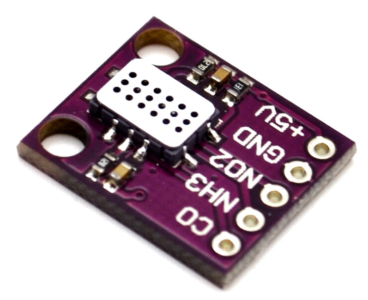
The board consists of the sensor with a few current limiting resistors, according to the reference design from the datasheet. To attach the sensor through I2C, an ATmega328PA that I had lying around, is used. For this I needed a small board to manage the heating control, the programming of the microcontroller as well as potential level shifting.
Schematic

The schematic above shows the wiring of the adapter board. The board is connected to the main air quality sensor through the 5pin connector at the top left. The MiCS-6814 sensor should always run at 5V so I need a pin for that. To allow for a lower main logic voltage, the VCC pin takes the voltage for the level shifters. The other pins are just a ground pin and the two pins for the I2C bus.
In contrast to the datasheet, the resistance values from the sensor are not read through one single ADC pin but through three separate analog inputs with their individual serial load resistors. The resistor values are taken from the document of paulvha.
PCB Design
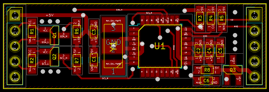
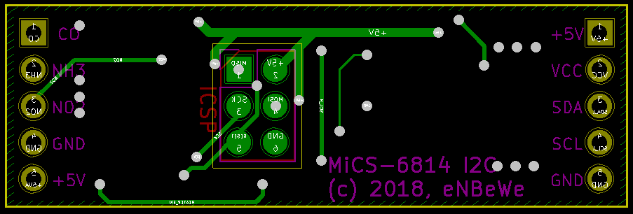
I designed my pcb in KiCad as can be seen above. The ICSP connector on the back is done as 6 pads, allowing for programming through pogo pins. For initial development, I just soldered a normal pin header to the pads.
My initial firmware on the controller is just a port of the original firmware from the Grove Sensor, allowing for reusage of the existing library. However, as I am currently getting more and more freaked out by the really poor code quality of the original library, I am currently doing a rewrite.
More on that later.